Monday 5 December 2011

Starting on the baseboard

My dad and I made the frame for the baseboard. Made from 8 1.8m x 32mm x 19mm wood, cut to my design, and screwed together. The 2x 30cm ends are bolted to the main frame, so can be removed for future expansion. To add more rigidity a 6mm MDF board will be screwed on top.

All in all to get it to this stage it took about 3hours. 

Baseboard shown with Full scale paper layout plan

Wednesday 16 November 2011

Factoid #8

Excluding the approach to Butts Junction, the line was entirely single track. Only Herriard station was provided with two platforms.

Tuesday 15 November 2011

Oh Mr Porter! Cliddesden Film stills

The Film Oh Mr Porter is a great research tool for working out what Cliddesden station landscape looked like at the end of the railways life. It also shows the scale of what the place was like. My model is going to try and recreate Cliddesden as it originally was, so things marked as Film props below will not be included. Although maybe in the future for a change of scenery I could replace the buildings with 'Buggleskelly' film props/ scenery/ buildings, and run the line with trains used in the film.
You can watch the movie (in parts) on YouTube

Monday 14 November 2011

Factoid #7

There was a speed limit on the line of 25mph, although in some places, especially when reaching certain level crossings was about 10mph.

Saturday 12 November 2011

Factoid #6

The Journey typically took 45 minutes to reach the end stations (Basingstoke or Alton). Today by car it would take about 20 minutes.

Friday 11 November 2011

Cliddesden 'Station' today - Hackwood Lane (2011)

A picture I took looking towards the station (towards the A339). framed between Station road on the left, with railway cottages and station masters house, and to the far right, Hackwood Lane and Level crossing. In effect the area I plan on modelling.

To begin with we were unsure as to how the line crossed Hackwood Lane, lots is written about the station road level crossing, as a fatality unfortunately happened there. But the only reference I could find for Hackwood lane, is a small map, of the 1911 layout. In fact there is no mention of it in the official inventory. So just to confirm that in fact it was a level crossing we took a closer look.

Foundations of railway shelter?  Floor is highlighted
Railway embankment, in woods looking towards
Alton, after just crossing Hackwood Lane
Hackwood Lane
Modern day embankment, the rail line would
have gone straight through the middle.

Although the picture shows a large embankment on one side, it drops on the other, modern day material was seen in the earth of the embankment, so we were pretty certain it was in fact a level crossing, and the embankment was made later. Hunting around further we found some foundations for a small building, on the side of the road, what we presume to be a shelter for the railway workers who worked the level crossing. If any body knows more details please contact me, as I might be completely wrong.

Thursday 10 November 2011

Factoid #5

The government paid £2000 per mile of track, just under 12 miles in total, to help efforts in WW1

Wednesday 9 November 2011

A little inspiration

A few weeks a go, we visited the  Farnham 37th Model Railway Exhibition, on show was plenty of N Gauge (2mmFS) layouts. To my amazement there was a layout that depicts a portion of a proposed branch of Mid Suffolk Light railway, known as Framsden. In many ways the layout is similar to Cliddesden, and the other stations on the Basingstoke and Alton Line. The detail, and size of Framsden is an inspiration for my layout. Here are some pics:


As some people have pointed out Framsden in 2mm Finescale. Thanks for the comments.

Sunday 6 November 2011

Factoid #4

A small section of the line exists as a memorial, in the middle of the Viables Roundabout in Basingstoke.

Friday 4 November 2011

LSWR 48' Brake Lav. Tri-Comp. - Final Part

The taller roof vents I believe are both part of the ceiling gas light holder and vent for fumes. The smaller vents coincide with those compartments that allow 'smoking' and simply vent the stale air from the compartment. They were all adapted from spare 00 gauge kit components that looked like vents but were designed for other purposes.

The roof is simply cut out from photo paper. It takes hole drilling for the vent spigots very well.


This was my first attempt at scratch building an 'n' gauge model. From normal viewing distances the coach looks good. Close scrutiny however, does raise eyebrows about the window frame edges. I'm sure this can be improved on the next build but there is no doubt etched brass body sides would be best.


We have also considered punched card or milled metal for the body sides and window cutouts but the specialist tooling required may be prohibitive.


You will see from the posting below that another M7 has been obtained. This one in Southern livery. That means I will be making a second coach, this time in Maunsell olive green with leaf spring bogies for the later period of the line.

To Part 1

Thursday 3 November 2011

Southern '37' M7

 My dad said, in a previous post:
"To increase variety for the model railway it would be nice to be able to run two M7s, one of each livery for the two periods."


Your wish is my command... Another troll through Ebay, and a Southern '37' 0-4-4 M7 made by Dapol, was up for auction. A few days later and I am now the proud owner. The M7 is exactly the same as the LSWR, but with different graphics. Although this was second hand, it was in pretty good condition, albeit the right vacuum pipe was missing, luckily we had a spare one to replace it with. This now gives the option of being able to run our model railway in the different periods (Pre and Post War).

...Now I just got to work out how to change the scenery at the same time.

Wednesday 2 November 2011

LSWR 48' Brake Lav. Tri-Comp. - Part 6


Two attempts to make the under-frame. Problem was the solebars that I initially made from card but proved too flimsy. When I scoured my scrap box for ideas I found some double o code 100 flat bottom rail and surprise, surprise it virtually matched the required style and dimensions. The wide flat bottom even looks like the full length step board of the prototype.


Parts for the entire coach, except the bogies, have been hand made from materials already in my possession.


For the under-frame only the most noticeable fittings have been modeled; floor (aluminium), gas tanks (balsa), vacuum pumps (plastic sprue) , V hangers and trusses (brass sprue), buffers (hornby oo track pins) and coupling hook (copper wire), all held together with Superglue.


The final part in this series deals with the roof fabrication.


To Final Part


To Part 1

Tuesday 1 November 2011

Factoid #3

The Basingstoke and Alton Light Railway, towards the end of it's life was used in 2 Films. Oh, Mr Porter! and The Wrecker

Monday 31 October 2011

LSWR 48' Brake Lav. Tri-Comp. - Part 5

When I created the artwork for the body side the coach number printed was 440. This identifies a coach from the first batch of 6 manufactured that were fitted with coil spring bogies rather than the later and more common leaf spring types.

I did not wish to scratch build the bogies, which are quite complex, so I looked around for r.t.r examples. A trawl around the web revealed how rare these are. I was fortunate in finding on Ebay a damaged coach from the old ROCO range that had two good bogies very close in style to that required.

They are about a foot too short in the wheelbase, which I can live with (no one will spot that in 'n' gauge!) and the coupler protrudes further than normal but as there is no corridor connection the increased gap between rolling stock can be tolerated.

The photo shows a dummy fit of a bogie before the underframe was fitted. The underframe is the subject of the next posting in this series.

To Part 6

To Part 1

Saturday 29 October 2011

LSWR 48' Brake Lav. Tri-Comp. - Part 4

I'm glad I made the seating for two reasons.

Firstly, they bring rigidity to the structure. The seats were simply made from Z folded 0.75mm grey board covered in red moquette fabric (reduced photo printed on sticky backed label).

Secondly, it gives an insight into the British class system of the early 20th century. The third class compartment accommodates (tightly) 10 passengers on two benches. I have shown it upholstered but would not be surprised if it was actually hard wooden benches.

Eight second class passengers per compartment were given the luxury of an arm rest between four, which was probably more use as a demarcation between couples.

The five first class passengers per compartment enjoyed two arm rests each and a share of a lavatory attached to their compartment via a connecting door. Luxury indeed for a slow (20mph) journey from Basingstoke to Alton.

The next part in this series takes us below floor level.

To Part 5

To Part 1

Thursday 27 October 2011

LSWR 48' Brake Lav. Tri-Comp. - Part 3

The interior walls help to keep the bodywork square.

I thought that with such a small model it would not be necessary to model the seating. When I looked through the windows and saw the carriage prints on the walls I knew that no seating would be an obvious omission. So, the next part in this series will be about adding the seats.

To Part 4

To Part 1

Wednesday 26 October 2011

Factoid #2

The railway track was pulled up to help efforts in the 1st World War, being re-laid in France.

Tuesday 25 October 2011

Full scale layout

Last night I decided to print out my favourite layout in Full scale. 34 A4 pages later, and I now have a full scale plan, an exact scaled (2mm:1ft) replica of the 1911 map. Doing this has certainly opened my eyes, to the sheer size, and what's going to be involved. In my head I thought I was making a much smaller railway. The good thing is I can adjust and amend as I feel fit without it costing money.

LSWR 48' Brake Lav. Tri-Comp. - Part 2

I'm using Kodak photo glossy paper for the body sides. It has some stiffness, is thin enough not to be obtrusive and takes clean knife cuts without snagging. On the other hand it is easily marked and the emulsion finish tends to turn to powder if scratched. This is a problem when trying to locate the wire grab handles in their locating holes because misalignment of the wire will scratch the printed surface.

To protect the surface (the ink is not waterproof) sticky backed clear plastic used for book covers is applied over the printed side. It gives a subtly shiny surface reminiscent of paint varnish that would have been used on the prototype.

Next, the windows are cut out. The scalpel point is pushed through at each corner in a slicing action rather than dragging the knife. This way there is no chance of cutting too far. Removing the blanks reveals the white edge of the paper. This was covered using a brown felt tip pen but, regrettably, the wet ink leeched between the paper and plastic covering in some places. Probably better to use a dry crayon or similar.

The grab handles are formed from 0.22mm brass-like wire used in jewelry making. This is stiffer than copper wire despite its small diameter. The locating holes are made with the point of a fine sewing needle and the wire tails pushed through and folded flat at the rear in a downward direction towards the bottom of the side.

Next the window glass is cut from clear plastic as one long strip about 1mm larger than the window apertures and stuck to the rear with strips of double sided tape.

Interior panelling (printed on A4 sticky label sheet) is laid over the rear. This fixes the tails of the grab handles and tidily hides the assembled parts.

The lower portion of the side needs to be slightly curved inwards. Placing the side over the edge of the table and gently pressing to form the curve works well and the tails of the grab handles, being stiff, help to fix the curvature.

Finally, the Guard lookout is formed up and stuck onto the side.

In the next part of this series all the bodywork is assembled.

To Part 3

To Part 1

Monday 24 October 2011

Cliddesden plans

Using the plan of the station from 1911, I have scaled it down, and using Microsoft Visio, worked out the best way to lay it all out and work out the best design for my situation.

In the future I plan on modelling the other station's  (Thorycroft, Herriard, Lasham and Bentworth), so the layout needs to be constructed with flexibility, usability and playability in mind. Being that the Basingstoke and Alton Light railway was for most part a single track line, this is not ideal for the usability or playabilty of my model railway. So, to add more interest I plan on making a loop, with a back siding, and the loop curves at the end of the table can be removed when the other stations come on-line.

I have applied a bit of artistic license, and moved Hackwood road a lot more closer. Otherwise I would have ended up with a board twice the size. I wanted to use it as it adds more interest to the layout, It'll just be a small compromise on reality.

My favourite plan:

Some other ideas:

Sunday 23 October 2011

Riding the line @ Winslade


Today we managed to go on a cycle along some of the The Basingstoke to Alton Light railway line. The part we took (as close as possible) was from Cliddesden Station, and along the Winslade bend/ curve. Unfortunately the line starts to go into a conservation area where we were not allowed.

Ummm - maybe we should start a group to reinstate the Basingstoke to Alton Light Railway as a walking Cycling path, any one with me?

Going on the ride opened my eyes to how steep some of the embankments are, and a better idea of how to model some of the area around Cliddesden station.

Here are some pictures of a chapel, bridge and embankment, all built at the time of the line.

You can see the ride path here:

View 21.3 miles Oakley to the Basingstoke to Alton Light railway line (part of) in a larger map


LSWR 48' Brake Lav. Tri-Comp. - Part 1

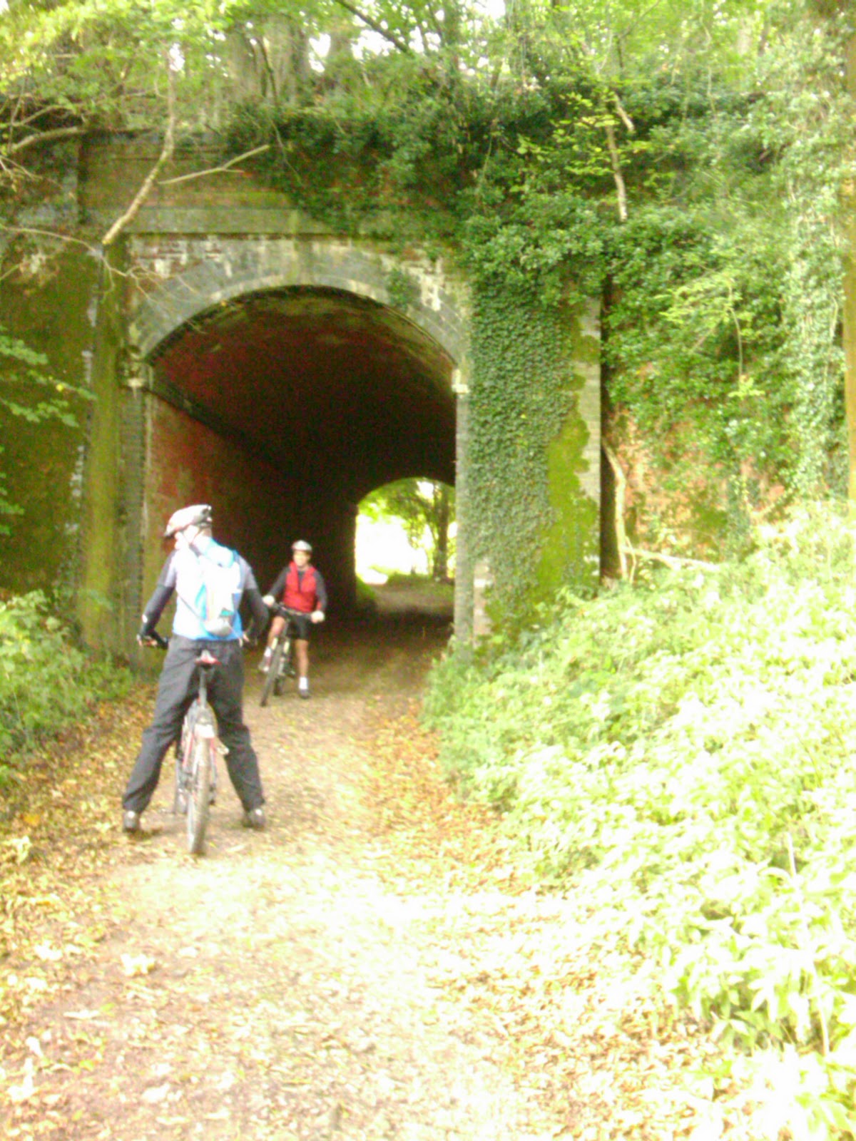
In the book "The Basingstoke and Alton Light Railway" there is one reasonable picture of the passenger coach used on the line in the 1920s. This enabled us to identify it as a LSWR 48' Brake Lavatory Tri-Composite built in 1891/92 to diagram 131.

For the 1920s it would have been finished in a green livery but since we have an LSWR liveried locomotive for the earlier period of the line we need a version finished in LSWR salmon pink and brown chocolate. Can't say for sure this coach was used on the line in the early 1900s but at least its LSWR and was used on minor railway lines.

Our first task was to find a plan so that a scratch built model can be made since no 'n' gauge r.t.r. or kit is available from the trade. A quick web search revealed that the December 1973 issue of Model Railway Constructor had a plan and there was a copy for sale on Ebay! This was duly purchased. There are also some good photos of a similar coach on the Bluebell Railway website including a few interior views.

Anyone who has visited my blog at amodelrailway.blogspot.com will know that I am an experienced 4mm scale modeller so to try my first scratch built 2mm scale model is quite a challenge with a whole different set of modelling standards and methods to learn.

The 4mm plan of the bodywork in the magazine was rescaled to 2mm using photo editing software and an overlay created and coloured. There is a myriad of recessed panelling that is represented with outline on the artwork rather than relief on the model. In 4mm relief is easily modelled but in 2mm it is impractical to do so (for my skill level and methodology anyway).

My approach to the build is to print the artworks using an ink jet printer onto photo glossy paper and these will form the bodywork. The artwork is created at 1200 d.p.i. but I feel a smaller resolution say, 300 may work just as well. The photo shows some of the parts. The beauty of this approach is that a second set of artworks could be quickly produced in green livery for the later period.

The next part in this series will cover fabrication of the body sides - There is more to it than just the printed artworks!

Author: DS

To Part 2

Saturday 22 October 2011

Factoid #1

The Basingstoke to Alton Light railway was the first line to open under the Light railway act, and the first one to close.

Wednesday 19 October 2011

Basingstoke to Alton Rail Line on Google Maps

Please feel free to collaborate on this map:

http://g.co/maps/5zbbf

I know it's not 100% accurate, so would appreciate some input.

If need be you can download the KML file and load into Google Earth, or into your GPS device.
Please note the line crosses private land in some places. Please only use marked footpaths, or by-ways, if you plan using the route for cycling, walking, running etc.


View Basingstoke and Alton Light Railway in a larger map

Tuesday 18 October 2011

Wagons


I recently purchased 4 different types of GWR wagon's, for the railway.
- 7 blank wagon
- Cattle Van
- Single Vent Van
- Long Truck Wagon

Need to find some LSWR and Southern wagons, and some private owner ones.


Monday 17 October 2011

Where is the Basingstoke to Alton light railway line?


I guess I should have found this out before I went on a cycle ride to try and find it ;-)

Well after a bit of research I have found some good resources that show the lines location.

Old-Maps.co.uk:
Old maps showing the line as it was around 1911. (you have to search each area)

Openstreetmaps.org
Up to date maps, showing the dismantled line. (Viables to Alton).

I have converted this information into a KML file which can be overlaid in Google Earth/ Maps or used for GPS devices. (Track not 100% accurate) - Just trying to find an easy way to get it online.

OK some trains


This was posted on amodelrailway.blogspot.com, and explains it nicely - Thanks Dad!

"Here is a recently acquired Dapol LSWR M7 locomotive - a real joy to behold for its fine details. For those not familiar with the size of 'n' gauge it is shown below a UK 10 pence coin.

It is destined for a yet to be built model of Cliddesden station. An 02 tank was desired, to be authentic for the Basingstoke to Alton Light Railway, but this is the closest r.t.r model available. Same wheel arrangement and similar features but a good deal longer at 36' 2" against 30' 8" for the 02.

The LSWR livery covers the period of the line from its inception in 1901 to first closure in 1916. The line reopened in 1924 to finally close in 1936. For this latter period a Southern livery locomotive is needed.

There was little traffic on the line and only an 02 locomotive was used to haul the single passenger coach and freight, disregarding a brief period when a H12 Railmotor conveyed passengers.

To increase variety for the model railway it would be nice to be able to run two M7s, one of each livery for the two periods."

Sunday 16 October 2011

The cycle route missing the line by 1 meter


This image shows the 'blue' (cycle) route which we thought hit the line, but we were out by about a meter, and never reached the line. 'White' line shows route of Basingstoke to Alton Line.

This is just outside Cliddesden, near Winslade.

Friday 14 October 2011

Welcome

Welcome to my blog about the Basingstoke & Alton Light Railway 1901 - 1936 (no longer running - deceased), modelled in N gauge.

I'm by no means a model railway expert, but for some reason, nearing the age of 30 my childhood interest in my N gauge train set has been reignited. Partly due to my fathers interest and his 00 gauge layout based on Misterton station, and surrounding line - www.amodelrailway.co.uk, amodelrailway.blogspot.com. And a few cycle rides trying to ride some of the line.

Choosing the Basingstoke to Alton Railway to base my model on, in particular to start with Cliddesden station, started with a Cycle ride to try and ride some of it. However our first attempt to find it, without knowing exactly where it was, lead us in the wrong direction, then we tried again some weeks later but this time getting within a few meters, but never actually being on the line (long since gone). This lead me to do some research to find where the line was. I did not really know the line existed, but other people knew off it. So, I gradually started to build up knowledge, I started looking into the history, and read a book about the line my father had in his collection. This started me to think about building my own N gauge model railway.

Although I still had some N gauge trains and wagons from when I was younger, none are of the era, or L&SWR or Southern liveried, so this endeavour means starting pretty much from scratch.

I invite you to join me on my journey...

Regards,
Ed